Senior Design I
Executive Summary
Download links: Senior Design I Documentation, Component Selection
The three‑phase power system is innately more efficient in power transfer when compared to its one‑ or two‑phase counterparts. A single phase system uses two conductors to create one AC power loop to transmit one unit of energy. In a balanced, three phase system three AC power loops are formed using three conductors transmitting three units of power. The advantage is clear. The three phase system has another powerful attribute which directly enable this project; three time varying vectors placed as position vectors in a complex plane each described with E_(a,b,c)=cos[ωt+θ_(a,b,c)], where θ_a= θ°,θ_b= 120°,and θ_c= −120°, the resultant vector will rotate with the frequency of the sinusoids (ω). Furthermore, if these sinusoids drive electromagnets placed as before, they generate a rotating magnetic field with the same rotational velocity. This is the core principle of all three‑phase AC motors; the rotating magnetic field generated by a three‑phase sinusoidal power source.
The three‑phase alternating current motor is the workhorse of modern industry. Its combination of high conductor efficiency, extreme reliability, smooth operation, and lack of on‑site waste disposal makes AC motors extremely popular for industrial drives of all types. Compared to DC motors for similar applications, AC motors tend to have all of the big wins in technology except one; speed and torque control. Speed and torque control in DC motors is of trivial complexity; just limit the current going into the rotor and the torque will follow. Speed and torque control of an AC motor is not nearly as simple. The three‑phase AC motor uses the intrinsic properties of the three‑phase balanced system to create a rotating magnetic field inside the stator. The speed at which this field rotates directly impacts the motors rotational speed. However, the speed of rotation is a function of the input sinusoidal signal's frequency. This simple fact makes speed control of AC motors a complex problem. Solving it requires varying the frequency of the sinusoidal power signals operating the motor‑that in and of itself is immensely more complex than simply controlling a DC current.
The solution is the Variable Frequency Drive (VFD); a very mature subject in electric machinery. VFDs perform the task of AC motor speed and torque control, they vary not only the frequency of input but the currents or voltages on each phase as well. The combination of varying the frequency and varying the amplitude of the power signal into the motor allows the control of speed and torque. Being that this system has two outputs (frequency and amplitude) and has one input (desired torque or desired speed) the control system which will operate it would seem initially complex. The problem of AC motor control is not easily solved intuitively as the time varying signals make mathematical modeling of the motor to generate desired motor signals for Proportional‑Integral (PI) controllers to use is very difficult and computationally expensive to implement in a stationary reference frame.
The solution implemented by Group F is to employ Field Oriented Control (FOC), also known as Vector control to dynamically model and control an AC induction motor of our choosing. Field oriented vector control was first enabled by a publication by R.H. Park in 1929 which detailed a mathematical model which could be implemented with a series of trigonometric reference frame transformations which allowed the motor torque and flux "components" of the sinusoidal power signals to be separated from each other as orthogonal, DC vectors from the origin in two dimensions [1]. This publication allowed for the first implementations of field oriented control. Because the flux vector and torque vector are orthogonal, the controller can hold one vector constant (usually the flux) and vary the other (usually the torque) independently. This allows the PI controllers to have a direct way to control just the torque which our motor will output. This fact alone simplifies control enough where the only methods which existed before its inception couldn't account for motor transient response at all and had to just de‑rate the components enough to bear it.
The VFD as implemented by Group F is a highly flexible design. By inputting nameplate data from any induction motor within a range of power ratings, we can dynamically model and control it with our system. Attached to a motor which tolerates extremely high turn down, we can expect exceptional dynamic performance from our drive. The drive could also be easily adapted to work with a synchronous motor as well. And the algorithm to control a synchronous motor would be slightly simpler given the lack of slip. The induction motor is just so much more prevalent in low to medium power applications.
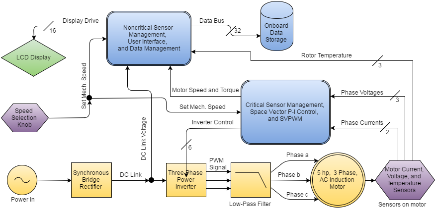
Overall Block Diagram

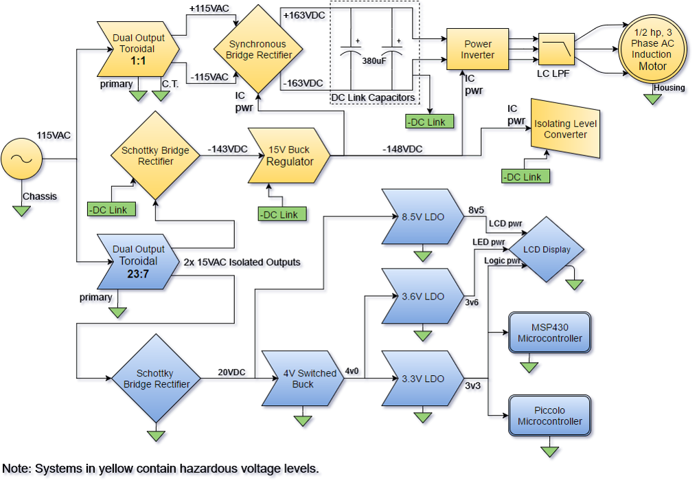
Power Block Diagram
