Conference Paper
Abstract — The objective of this project is to make an affordable Ground penetrating radar (GPR) system that can be used in graveyards and is more reliable that traditional grave dowsing. The solution is expected to utilize the processing power of an iOS device for the digital signal processing and combine it with inexpensive hardware to determine signals sent to and from the ground. The group chose this project because it combines Computer Science and Electrical Engineering disciplines and combines them for a very unique purpose.
Index Terms — Receiving and Transmitting Antennas, Pulse Generation, Digital Signal processing, Microcontrollers, Ultra-wideband radar, Wireless Communication
Introduction
The goal of the project is to provide a cheaper alternative to already existing GPR technologies on the market for use in a cemetery. Typical GPR or Ground Penetrating Radar can cost up to $20,000 1. Our goal is to create a much more affordable alternative, under $100 preferably. Our GPR surely will not have the number of capabilities that these extravagantly priced models have, however ours will serve the purpose that it needs to at a price that an average person can afford. Traditional Grave Dowsing only has 50% reliability, which we want to increase to a higher efficiency rate.
The initial design of this project takes a control unit of some sort, sending signals into the ground, receiving echo signals, and compiling the data from these many echoes and sending it back to the control unit. The software application on the iOS device will then process the data and determine whether or not there is a casket or gravesite below. We need to display this through an application that we develop to determine whether or not there is a casket at the grave site. We have determined that this project will have many additional features that will be implemented within the UI (User Interface) that we will develop. We plan on developing this for the Apple mobile operating system or iOS. We believe that this will open the door to create more usability for people to make use because users can use their cellular phones as well if they do not have an iPad readily available. The UI is supposed to be relatively elegant in design and a layout that is easy to use and will not require documentation to use.
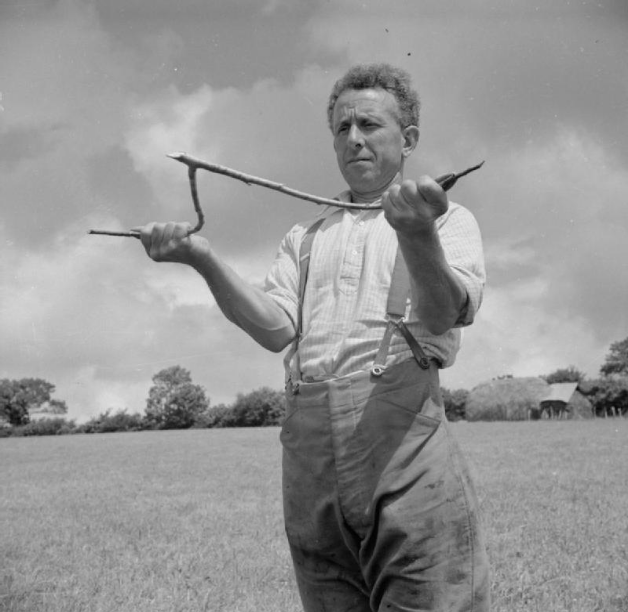
Figure 1 Traditional Grave Dowsing 2
IEEE Safety Requirements
It is necessary for our device to meet the WiFi standards to not only abide by FCC regulations but to also create compatibility between our device and the computer or iOS that we were sending the data to. The iOS device and personal computers are all hardwired to recognize and receive signals of predetermined frequencies and bandwidths so we had to make sure we met those specifications so our data can be correctly received. Also due to the nature of our project, we are covered in the FCC regulation, Part 97, Section one where it states, “Continuation and extension of the amateur’s proven ability to contribute to the advancement of the radio art” 1.
The Radio frequencies at which our device will be operating is listed as VHF/UHF under the ITU guidelines. According to the ITU, VHF stands for Very High Frequency, which ranges from 30 mHz to 300 mHz, and UHF stands for Ultra High Frequency, which ranges from 300 mHz to 3 gHz. According to IEEE guidelines we will be using an UHF as well however this incorporates frequencies between 300 mHz and 1 gHz. Lastly listed in NATO standards we are operating in the B and C bands between 300 mHz to 1 gHz. We are covered by FCC regulation again due to Part 97, exempting us due to amateur radio purposes.
Hardware Components
DC Power Source
Power is the first necessity for this project to be functional. The battery will be supplying power to everything in the base of our hardware section. The one we chose to power our project is the APX1280 Lead Acid Battery, a 12 Volt 8 Ah rechargeable power source capable of meeting the minimum power and battery life goals we have set. All of our electronic in total look to draw a total of 15 Volts, making the step up from the DC-DC converter necessary to power it all. The main reason we chose Lead Acid over more robust technologies like Lithium Ion were for cost effectiveness. Although Lithium Ion batteries normally provide a total package that is lighter weight wise than Lead Acid alternatives, comparable Lithium Ion Batteries were priced well above what we hoped to spend on a battery, and the APX1280 Lead Acid battery provided a cheaper alternative that would still meet our needs with the tradeoff of being a little heavier at 2.26 kg.
DC-DC Converter/ Voltage Regulators
The DC-to-DC converter and Voltage Regulators are necessary for both regulating the output voltage of the battery into the MCU and stepping up the voltage to meet the minimum draw requirements to run our electronics package. The MCU only requires 3.3 volts to run so we will use a voltage regulator to limit the voltage in. Our electronics package consists of our transmitter and receiver units. The transmitting unit, which is comprised of the pulse generator and tx antenna, requires a steady voltage source of 15 volts which will be supplied through a DC-DC converter stepping the voltage up from 12 to 15 volts. The receiver unit will require similar measures.
Pulse Generator
Our project will be generating, transmitting, and receiving signals between the frequencies of 50 MHz to 500 MHz so it will be necessary for us to utilize VHF/UHF capable radio as a signal generator to meet our needs. The pulse generator is so important because it is what creates the pulse necessary for imaging. The pulse width for our intentions must be between 2.5 and 5 ns to meet our frequency requirements. The design we chose for the pulse generator is based off of the circuit designed by Chinese researchers at the University of Chinese Academy of Sciences [3]. The design takes in a square wave trigger and in a couple steps transforms it into a high voltage Gaussian pulse that will provide good depth and resolution for reception in imaging. The circuit for the pulse generator is shown in figure 2.
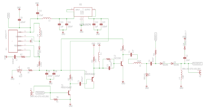
Figure 2
TX and RX antennae
In our TX antenna, it is important for us to utilize a directional antenna to serve our purposes best. The directional antenna would allow us to best control where we want to scan below the surface which is crucial in determining the location of something. After researching viable options for our TX antenna, all were above our price range so we are choosing to fabricate our own. We decided first on designing a bowtie copper antenna with a center frequency around 200 MHz, however the amount of material necessary at the current price of copper was too expensive, so we ended up designing a smaller copper patch antenna with the same rf properties.
In our RX antenna, again it is important to either choose or create a directional antenna to reduce multipath issues associated with reception. After looking at the market for antennae, the best option for us would be to fabricate our own RX antenna as well. We decided to make a replica antenna for our rx unit as our tx unit. The patch antenna will have a center frequency at 200 MHz and will be made from fr4 copper substrate.
Analog/Digital Converter
The A/D Converter will take the analog signals received from the antenna and convert them into a digital value that can be used as data for interpretation. There are many things that go into the decision of the A/D converter like what dynamic range will be necessary to meet your needs or to what accuracy you want the converter to function. We decided to stick with the 12 bit ADC that came built into the MCU as our means of digitization.
Sample and Hold
We decided to sample our incoming signal with equivalent time sampling rather than real time sampling because we could not obtain a digitizer or oscilloscope and we were unable to find a fast enough ADC to sample efficiently within our price range. The Sample and Hold circuit is crucial to our impulse gpr because it is what feeds the signal into our ADC at a constant rate so we can accurately read in the signal data for interpretation. It is much more cost effective to sample and hold at ultra-fast rates and then feed the data in intervals into the ADC than it is to have the ADC digitizing all incoming signals at an extremely fast rate.
Microcontroller
The microcontroller (TI CC3200) is going to be mounted onto the PCB and be executing operations throughout the hardware portion of our design. It is to be the I/O controller unit at the base of the design. This is the main unit we will be communicating with from the control unit. The embedded programming will be within the microcontroller unit, which will be responsible for performing the multi stepped tasks that the control unit will call with simple commands. An example is when the operator performs a search in the control unit, the MCU will automatically perform all the necessary steps to complete the search.
It will be able to request to turn on the antenna and off as well as receive signals from the Control unit. Control signal CS1 will turn on the antennas while CS2 will turn them off.
This will be also be our method of communicating from the iOS device to our hardware. We chose to use a MCU with Wi-Fi capabilities to ease the process of communication for the high-bandwidth and quicker communication between devices. This MCU will be responsible for transferring any data back and forth for the control unit to the electronics package.
Low Noise Amplifier
The Low Noise Amplifier (LNA) is an amplifier that reads in specific signals and amplifies them to make them more usable for sampling. The LNA that we chose for our project operates between the frequencies 1-2000 MHz so it should serve us well in amplifying the signal we retrieve from the ground to make it more readable for our ADC.
Printed Circuit Board (PCB)
All the major electrical components will be mounted to a printed circuit board (PCB). The PCB will be responsible for housing the processing components as well as providing the capability to handle all the power distribution and regulation from the GPR’s power source. We will have all sorts of hardware components such as the microcontroller (MCU) as well as the Wi-Fi transceiver which we will go into detail about later. These parts will need to be soldered on to ensure them from moving and we will then be able to begin communication from the iOS device to the antennae and vice versa. This is the centerpiece of our project. From the PCB we will make it possible to manually program the settings of the GPR with some sort of connectable port. The PCB will be the main hub of all the hardware’s functions.
Software Detail
The iOS software is divided into four major layers: Logic, Models, Views, and Input/Output. Each layer contains one or more modules, which represent further logical divisions of code responsibilities. Each module should be as self-contained as possible and only interact with other modules or layers using public APIs. The high-level relations of these layers is shown in Figure 3.
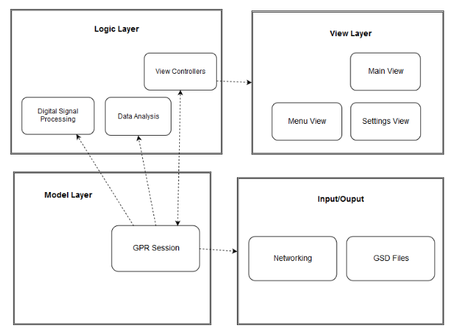
Figure 3
Model Layer
The model layer contains the models of the model-view-controller (MVC) design paradigm. Models are objects that encapsulate the application’s representation of its world and contain methods dictating how to manipulate them. In this application, the primary model is the GPRSession. A GPRSession object represents a single session of GPR data collection and holds all associated information. It holds data about settings being used, start date and time, starting location, all GPR readings, and results of data analysis: that is, where any graves have been detected.
See figure 3 for a class diagram of model layer classes. An active GPRSession, that is, one that is still receiving GPR data, has an input stream associated with it. While the session has not been terminated, signal data is read from the stream as bytes. The signal data is sent to the digital signal processing module for processing. After processing, the raw GPR data may be compressed and saved to a temporary file. The processed data is sent to the data analysis module and scored. If the score exceeds the scoring threshold for the current detection mode, a grave is considered to have been found. In this case, a UIEvent is sent to the ViewController, which handles getting that information to the human user, and the GPRSession records the location of the successful grave detection.
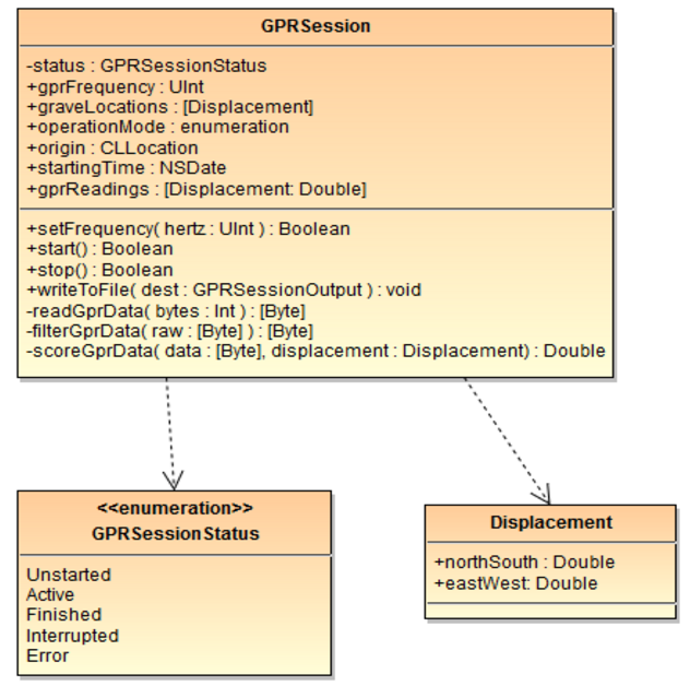
Figure 4
Logic Layer
The logic layer contains modules that handle data processing and analysis. The View Controllers module corresponds to the controller portion of the MVC paradigm. There is one controller for each view in the view layer: MainViewController, MenuViewController, and SettingsViewController. The role of each ViewController is to read state from the model, which holds underlying application data, and updates the corresponding view to display the appropriate information. Whenever a UI event occurs, the ViewController for the active View decides what model or application code to call and updates the view based on the results of these actions.
The Digital Signal Processing module contains code to filter and transform raw signal data so that it is more conducive to analysis. One public method is exposed: filter(), which takes an array of bytes (the signal) and an Enum (the filtering mode to use), and returns an array of bytes (the filtered signal).
The role of the Data Analysis module is to analyze sensor data and decide whether a noteworthy object has been detected. Like the DSP module, it exposes one primary method: analyze(), which takes an array of bytes (processed signal) and an Enum (analysis mode), and returns a single double representing a score for the given data. Higher scores correspond to higher likelihood that the given signal data was the result of the GPR unit passing over a grave site.
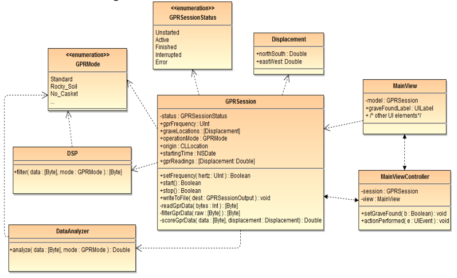
Figure 5
View Layer
The view layer contains classes corresponding to the views of MVC. These classes define the visual representation of the application. Each view corresponds to a view that a user might encounter as he or she interacts with the application. The MainView is the screen that is usually displayed during typical usage. Its main purpose is to keep the user informed about session progress and alert the user when a grave is located. To this end, MainView is dominated by an indicator of whether a grave has just been found. It also features displays of session duration, whether data is still being received, and how many graves have been found so far. The MenuView allows the user to navigate among other views. The SettingsView allows the user to adjust global and session-specific settings.
Input/Output Layer
The input/output layer contains classes that handle where incoming data comes from and where outgoing data ends up. It exposes several interfaces:
- GPRDataSource, some source that produces a stream of GPR data and may be told to
start(),stop(), orsetFrequency(). - GPRSessionSource, some source which holds a representation of a GPRSession. A previously recorded session may be loaded by calling
loadSession(). - GPRSessionOutput, which allows saving session information via
saveSession(). - GPRDataOutput, which allows saving raw or processed GPR data via
writeGPRData()
Software Requirements
User Friendly Interface
We plan to design our UI within Xcode while utilizing elements that can be implemented with the help of Adobe Photoshop by any other logos for certain tabs we need to design.
The application’s targeted users are people who work at cemeteries so technical skill is not assumed to be advanced. It is important to take this into consideration when designing the user interface so that the user can easily start getting things done with the application. Users expect applications to be responsive, quick, and easy to use. Part of the reason an iPad/iPhone was chosen is their responsive and aesthetically pleasing standard UIKit that many people are already familiar with. If the UI is not well thought out and well executed, people will have issues with using the application.
A well-designed UI can often overcome a not so friendly underlying structure. As far as the user is concerned, the software should be an efficient way to complete their job. Software should not hinder the completing of a task, nor should it present obstacles to the user. A good interface is a simple interface. The best interfaces are almost invisible to the user. They avoid unnecessary elements and are clear in the language they use. By using common elements in the UI, users will feel more comfortable and are able to get things accomplished much faster.
Controlling the GPR
It is required for the software to be able to control the device. The user will have options to turn on/off the device, start a scan, and change settings. This requirement also inherits from the user friendly aspect, so of course these controls must be simple to use.
Receiving and Processing Data
GPR data will be received via a wireless local area network (using the WiFi standard) established with the hardware unit. On the iOS application end, the Bonjour framework will be used for network discovery and resolution 1. When the connection is first established, the frequency setting will be communicated to the hardware unit. After the connection has been established, the GPR unit will send null-delineated radar traces over the WiFi connection. A buffered input stream will be the application-side endpoint for receiving data. From there, it will be processed, analyzed, and saved.
Raw data for each radar trace will be run filtered and transformed in the digital signal processing (DSP) module within the iOS application. Performing DSP on the iOS device rather than the embedded hardware unit provides more freedom in choice of filtering and transformation algorithms, as some may be too slow or demanding on the embedded system. The Swift Accelerate Framework provides packages with FIR and IIR filters, Fast Fourier Transform, and other useful DSP tools. At present, the most effective filtering algorithm is undecided. The DSP module will be written to implement several different filtering configurations and as soon as we have sample data from a working prototype, we will be able to compare to see what gives the most accurate results. In the course of testing, if we discover that different signal processing configurations provide better results for different types of soil or for finding different types of objects, we will include these configurations as modes (with user-friendly names) selectable from the settings menu.
Once a portion of the digital signal has been processed, it may be analyzed to form a representation of underground features. Radar pulses propagate from the antenna and bounce off of obstacles. Some of the waves are scattered back to the antenna, and from these waves we can determine several things. First, we can estimate distance, which is linearly related to the time between pulse output and return (waves travel at the speed of light and cover the distance there and back, so d = C*t/2). Secondly, a sudden change in apparent distance should typically indicate the edge of an object. When a number of readings are taken in a straight line, the depth readings form a sharp parabola around any object encountered. This can be seen in GPR data visualization tools.
Measurements from a given location will be stored and indexed by 2D location. By comparing measurements at several proximal points, the data analysis module will generate estimates of likelihood of an object or the edge of an object being present at any surveyed location. During testing, we will calibrate the function from measurement discrepancy to certainty estimate. As more data points are collected, the data analysis module will modify its estimates. With lots of 2D points, estimates of object size and shape can be made. Size and shape analysis may be difficult to do concurrently with basic analysis, so this analysis may need to be activated manually. Furthermore, this analysis may be difficult, unreliable, or require too many samples to be practical. For this reason, size and shape analysis are left as a stretch goal. Human users may be able to do their own size and shape analysis by noticing that the device detects objects/edges in a certain shape.
Data Storage Format
A GDS file consists of two sections: the header section followed by GPR data. These sections are separated by the start of heading ASCII character (0x01 in hexadecimal). Within the header, data records are terminated by the end of group character (0x1D). Records that are repeated (detected grave locations) are terminated within their group by the end of record character (0x1E). For readability, these separating characters are replaced with spaces between records in the description below.
The header begins with a magic number for verification: 0xCD15. Next is the date the session was recorded, saved as an ASCII string in ISO-8601 date format. Next, the location where the session started. This starting location is stored as two doubles representing latitude and longitude. Location coordinates will be stored as NaN if GPS data is not collected. The next record is the frequency in Hertz. GPR frequency is typically in the 100 MHz to 2 GHz range 5,6,7,8, and lower frequencies should be ideal for caskets of typical size and depth, so an unsigned 32-bit integer will be sufficient (up to about 4.29 GHz).
Frequency is followed by any other session settings, such as filtering mode. Session settings are key-value pairs, where the key is a unique alphanumeric string terminated with a colon (:) and value is an integer corresponding to the setting’s enumeration. There are currently no settings other than frequency, but as discussed in 3.4.4 and the software testing section, the user may be allowed to choose from among two or more filtering modes. As these and other settings are added, old settings will remain the default (enumeration 0) for backwards compatibility and future extensibility. The settings section is terminated with an additional end of group character.
The header is terminated with the start of heading character. Following this is radar data. If testing indicates that uncompressed bytes take up too much space, the specification will be updated to require that radar data is compressed using a standard Lempel-Ziv compression algorithm. Radar data will be a sequence of bytes whose length b matches that listed in the header section. These bytes correspond to the signal data transmitted by the GPR unit after they have been filtered and transformed by the DSP module. Processed data will be saved to avoid spending time processing the data again. If testing determines that raw, unprocessed data is most useful (and not impractical), the file specification will be changed to specify that unprocessed data is contained instead.
Integration of Hardware and Software
Combining the two portions of the project and hardware is done with the connection of the iOS device (which is also acting as our control unit) to the hardware. It will communicate to the PCB and will know that it wants to send a signal. The PCB will then communicate to the antenna to send plenty of signals into the ground. Almost instantaneously, the receiver will start detecting the echoes from the signals.
As the signals start returning to the receiver, it will begin to process the information and send it back to the PCB. The PCB will then communicate back to the iOS device and through the application it will formulate an image and with that image it will begin to perform data analysis where it will find out if there is infact a casket in the ground or not.
Hardware is integrated into the project via the PCB, DC to DC converter, battery, and WiFi components. These parts are all necessary for communication efforts of iOS device to antenna and receiver back to iOS device. The power from the battery is also necessary to power everything in the project. We won’t need as much hardware as other GPRs on the market because this project’s plan is to rely very heavily on its software.
Software is integrated to this project in a very unique way. We are to be developing a mobile application on the iOS device and utilize its processing power while making our code so efficient it would be capable of doing everything on its own and not needed extra hardware as well. We plan on doing this to help tremendously with the cost. This is what separates us from the majority of GPRs on the market and it is why we believe we will be significantly cheaper than the rest of them as well.
Frame
All of the components will need to be housed on some sort of frame for protection and transportation. The frame will most likely be fabricated from aluminum and either be welded to make one solid frame or bolted together for easy breakdown and buildup. Fixed to the frame would be some sort of plastic cover to protect the electronic components within the heart of the frame.
A certain means of transporting the hardware such as wheels or something that can be slid is also necessary. The wheels would be mounted on some sort of axle that would be fixed to the frame if we choose that option. If we choose the sliding method, the frame will be mounted onto a low friction plastic that would allow the GPR to slide easily on the grass. On the frame it will be necessary to attach some sort of handle for easy dragging or rolling. Most of all, every part of the frame and movement parts will need to be rugged for heavy use and abuse.
Conclusion
This project although it has taken a lot of time has taught many valuable lessons that can translate into the work force no matter what the field. This process teaches conducting professional meeting and proper technical writing skills as well. Another noteworthy skill that is obtained through this process is the ability to filter out the bad ideas, pursue the good ideas, and research the best possible outcome in order to obtain a working prototype. We have learned a lot throughout our tenure at the University that helped us a lot with the technical portion. It also has given us a great deal of experience in building certain projects that integrate hardware and software to achieve a greater purpose.
The Engineers
We wish to acknowledge the advisement and help from Dr. Heinrich as well as UCF Alumni Ryan Borden.

Daniel Seoane, a senior Computer Engineering student at the University of Central Florida. He is currently working at Siemens Energy as an IT intern and he will continue working there after graduation as a Java and Python Developer for the Siemens Teamcenter Software. He is currently a student member of Theta Tau, a Professional Engineering Fraternity.
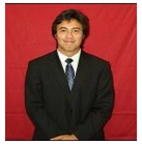
Colburn Schacht, a senior Electrical Engineering student at the University of Central Florida. He has also interned at Siemens Energy over the last 3 years. He is currently a student member of Theta Tau, a Professional Engineering Fraternity.

Stefan Lowe, a senior Computer Science Student at the University of Central Florida. He is currently on the UCF programming team and will be interviewing with companies like Facebook, Microsoft, and Google in the next coming months for Software Engineering positions.
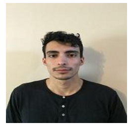
Lucas Rosa, a senior Computer Science Student at the University of Central Florida. He is currently working at a start-up based in Miami, FL doing work with Ruby on Rails and React-Native to develop a platform for creating applications for customers. He has interests in programming languages and linguistics.
References
-
“Amateur radio service.” Code of Federal Regulations. Title 47 § 97.1. 21 Oct. 2015
-
Whittaker, William E. ‘Grave Dowsing Reconsidered.” Office of the State Arcaeologist, University of Iowa, Iowa City. 2005
-
Xinfan Xia, Lihua Liu, Shengbo Ye, Hongfei Guan, and Guangyou Fang, “A Novel Subnanosecond Monocycle Pulse Generator for UWB Radar Applications,” Journal of Sensors, vol. 2014, Article ID 150549, 4 pages, 2014.