Objectives
- To understand the basics of AC (alternating current) circuits.
- To use an oscilloscope to display and record a waveform.
- To use an oscilloscope to measure frequency, period, voltage (magnitude, peak-to-peak, maximum, minimum, and etc), DC offset, etc, of the waveform.
- To use a digital multimeter to measure AC voltage and current.
Equipment
- Function generator
- Oscilloscope
- Digital multimeter (DMM)
Background
I. AC circuit basics
An AC (alternating current) is a function of time. In AC circuits, the voltage and current sources are time-varying, with the most common being a sinusoidal variation. Other time-varying applications, depending on the application, include the square wave and the triangular wave.
A sinusoidal AC voltage or current is described by its amplitude, frequency and phase, for example,  , where A is the magnitude,
  the angular frequency and
  is the phase. Special attention must be paid when measuring the voltage or current of an AC circuit, as three different forms of voltage or current may be obtained from a measurement, namely Vmagnitude or Imagnitude, VRMS or IRMS or Vpeak-to-peak or Ipeak-to-peak. They can be converted from one form to another using the following equations:
For square waveforms,


For sine waveforms,


For triangular waveforms,


II. Function generator
A function generator is a piece of equipment used to generate electrical waveforms. It is widely used in development, testing and repair of electronic equipment, for example, as a signal source to test amplifiers, or to introduce an error signal into a control loop. The function generator we are going to use for this lab is a Tektronix AFG 3022B, as shown in Figure 2 – 1. It is able to provide 12 different standard waveforms, with dual-channel capability. Sine, square and triangle waveforms (3 most used waveforms in this lab) can be selected from Function section. Both frequency and amplitude adjustment buttons are in the same section below ‘Run Mode’ section, which can be set either by the numeric keypad or by the knob above that keypad. The two arrows right below the numeric keypad can change which digit is to be adjusted. The ‘On’ button will turn each channel on or off, and ‘CH1/CH2’ button decides if it is a single or a dual channel output. Detailed functions will be shown in the EXPERIMENT section.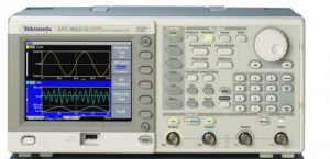
Figure 2-1 Function generator
III. Oscilloscope
An oscilloscope is a type of electronic test instrument that allows observation of constantly varying signal voltages. Usually a two-dimensional graph of one or more electrical potentials is displayed using the vertical or ‘Y’ axis with time along the horizontal or ‘X’ axis. In most instances, an oscilloscope shows events that repeat with either no change or very slow changes. Thus, the exact wave shape of an electrical signal can be observed. In addition to the amplitude of the signal, an oscilloscope can show distortion, the time between two events (such as pulse width, period, rise time, and etc), and relative timing between two related signals. The oscilloscope we are going to use for this lab is a Tektronix DPO 4034 Digital Phosphor Oscilloscope, as shown in Figure 2 – 2. It has 4 analog and 16 digital channels for analyzing both analog and digital signals. Detailed functions will be shown in EXPERIMENT section.
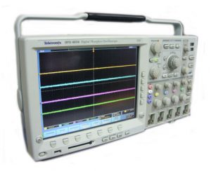
Figure 2-2 Oscilloscope
Preparation
- Calculate the RMS voltage of the following waveforms that have a peak-to-peak voltage (Vpp) of 10V:
- Sine wave;
- Square wave;
- Triangle wave.
- Calculate the period of a waveform with the frequency of:
- 100 Hz;
- 1 kHz;
- 100 kHz.
Simulation
Perform circuit simulations to verify the results obtained in PREPARATION.
Using a 1kHz, 10 Vpp sine wave as an example, perform the following steps in LTspice.
- Construct a circuit consisting of an AC voltage source, a resistor and a ground.
- Set the voltage source to output a 1kHz, 10 Vpp sine wave.
- Go to “Simulate” and select “Edit Simulation Cmd”. Under transient analysis, enter appropriate values for start time, stop time, and maximum timestep to obtain a waveform with 5 cycles.
- Click on “Run”.
- Move the cursor to the top node and click on the node when the probe symbol appears.
- To obtain a RMS measurement, hold down the “Ctrl” key and click on the label of the trace.
- Repeat steps 1 – 6 for a square wave voltage source and a triangular wave voltage source.
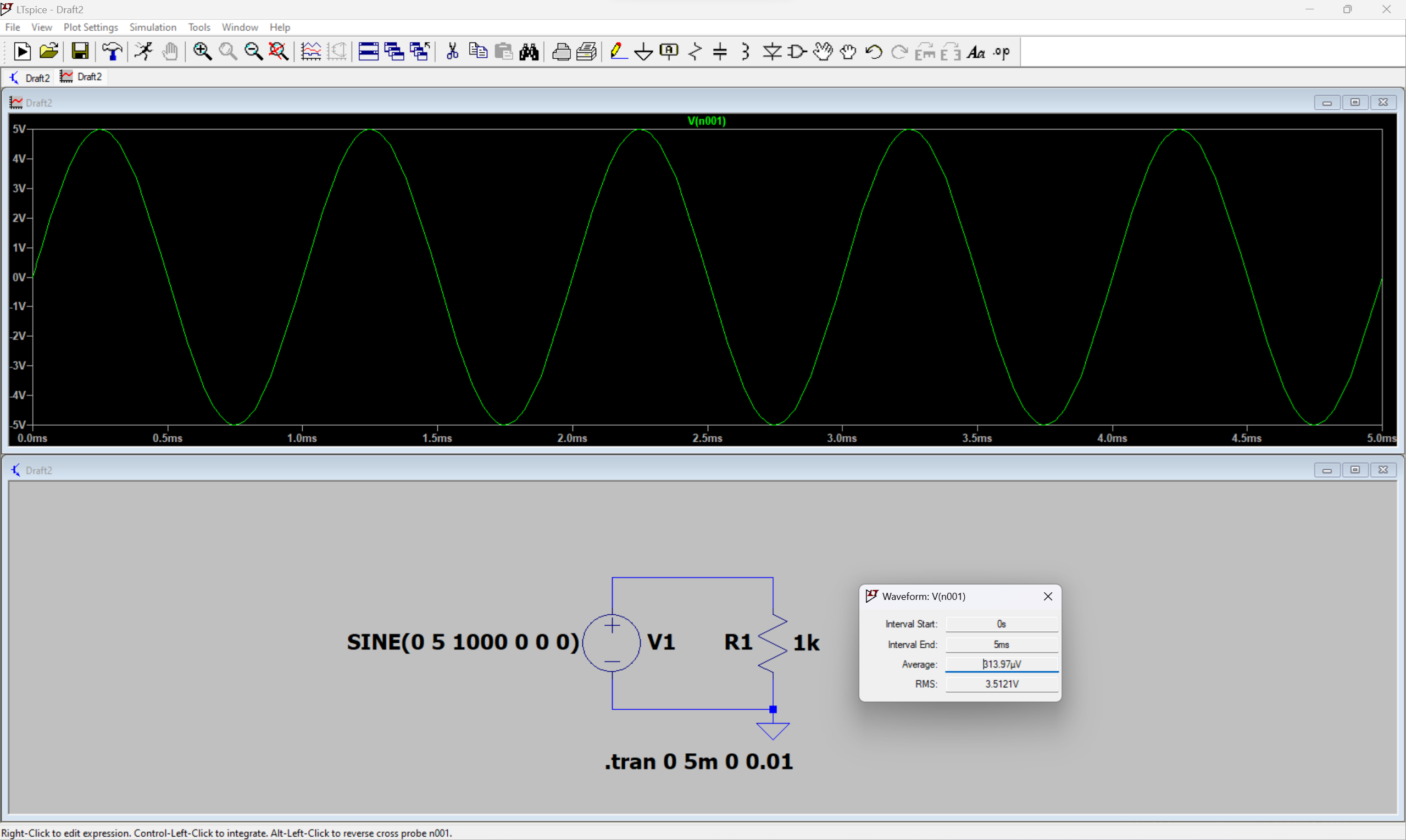
Figure 2-3 AC Waveform Measurement
Experiment
A. Waveform display and measurement
- Click the ‘Default Setup’ button located below the LCD screen on the oscilloscope to clear all the settings made by the previous user. For the same purpose, click the ‘Default’ button on the function generator, which is located on the left of the numeric keypad, and then click Enter on the right of the keypad.
- Set the function generator to run in the ‘Continuous’ mode by clicking the ‘Continuous’ button under ‘Run Mode’. The default mode is the ‘Continuous’ mode.
- Set the function generator to produce a sine wave by clicking the ‘Sine’ button under ‘Function’.
- On the function generator, click ‘Output Menu’ located on the right of the LCD screen, select ‘Load Impedance’ then ‘High Z’ option. Click the ‘Top Menu’ button to return to the waveform display screen.
- Connect Ch.1 of the oscilloscope to the function generator output. Polarities (positive and negative) of both probes must match, i.e. positive to positive, negative to negative. Turn on Channel 1 output by clicking the ‘On’ button of Channel 1 on the function generator. Click the ‘Autoset’ button on the oscilloscope to automatically display the waveform on the LCD screen. How many cycles are displayed?
- Click the ‘Square’ button under ‘Function’ on the function generator. What waveform do you observe on the screen of the function generator and oscilloscope?
- Click the ‘Ramp’ button under ‘Function’ on the function generator. What waveform do you observe on the screen of the function generator and oscilloscope?
- Set the waveform back to sinusoidal. Click the ‘Autoset’ button if needed.
- Click ‘Ch1’ button (yellow) on oscilloscope to bring up the setting options for Ch1. Click it again, what do you see on the screen? Click the button once again, did the waveform show up again? With the options for Channel 1 available on the bottom of the screen, set coupling to DC, and keep the rest at the default setting.
- Various measurement options for all four channels can be set on the oscilloscope. To do this, click ‘Measure’ button in ‘Wave Inspector’ section and press ‘Add Measurement’ button to bring up the menu. Use the ‘Multipurpose a’ knob to select the source (Ch1, Ch2, Ch3 or Ch4, whichever is available) and ‘Multipurpose b’ knob to select the measurement type. Using the ‘Multipurpose b’ knob highlight the frequency, period, amplitude, mean and RMS, and click on ‘OK Add Measurement’ each time to bring up the readings on the screen. When finished, click on the ‘Menu Off’ button to turn off the menu. (NOTE: the amplitude definition might be different from that in your text book. Make sure to check the definition on the oscilloscope when selecting this measurement.)
- Vary the frequency and then the amplitude on the function generator. It can be done by clicking on the ‘Frequency/Period’ button or the ‘Amplitude/High’ button, then either type in the number using the numeric keypad or adjust the knob above that. How does the waveform change on the oscilloscope screen? Do the readings on the bottom of the oscilloscope screen change as well? Adjust manually the vertical and/or the horizontal scale if needed. (NOTE: the readings on the oscilloscope will not be accurate if the waveform is not properly displayed on the LCD screen, e.g. too few cycles or the waveform exceeds the screen in the vertical direction.)
- Vary the channel scale knob in the ‘Vertical’ section and the time scale knob in the ‘Horizontal’ section on the oscilloscope. How does the waveform change on the screen? Do the readings on the bottom of the screen change as well?
- Now, with all the measurement displayed on the screen, set the function generator to output a 1 kHz, 10 Vpp sine wave. (Try to keep about 2 – 5 cycles of sine wave displayed on the oscilloscope screen by adjusting both the vertical and horizontal scale knobs in order to obtain an accurate reading.) What do you read for frequency? What do you read for amplitude voltage?
- Click the ‘Menu’ button under ‘Trigger’ on the oscilloscope. Adjust the ‘level’ knob on the oscilloscope. What do you observe when the level line is within the magnitude range of the waveform? How about when it moves outside the magnitude range? Move the level line until it is slightly within the magnitude range and the waveform display is stable.
- Keeping the level the same, slowly decrease the amplitude of the input signal on the function generator by adjusting the knob above the numeric keypad when ‘Amplitude’ is high-lighted on the screen (if not, click on the ‘Amplitude/High’ button). What do you see on the screen? Describe what you observed in step 14 and 15, and explain why.
- Adjust the level line back to the zero and the signal amplitude back to 10 Vpp.
- Adjust the ‘DC offset’ on the function generator by clicking the ‘Offset/Low’ button and set the value to 2 V. What do you observe on the screen of the function generator and oscilloscope?
- Refer to step 9 and set CH1 coupling to AC. What do you observe on the oscilloscope screen?
- Set CH1 coupling back to DC. What do you observe on the oscilloscope screen?
- Explain the difference between DC and AC coupling.
- Set the ‘DC offset’ on the function generator back to zero.
B. Voltage measurement
- Set the function generator to output a 10 Vpp sine wave.
- Display the output on Ch.1 of the oscilloscope.
- With DMM set to measure AC voltage, measure the output of the function generator. Which measurement on the oscilloscope (refer to step 10 of Part A) is this DMM reading equal to, Amplitude or RMS?
- Set the function generator to output a 10 Vpp square wave first, followed by a 10 Vpp ramp wave. In each case, what is the reading on the DMM? Are all the measurements consistent with those calculated in PREPARATION?
C. Frequency measurement
- Set the function generator to output a 1 kHz sine wave. Record the frequency and period readings from the oscilloscope.
- Change the frequency on the function generator to 100 Hz and 100 kHz. What are the frequency and period readings? Adjust manually the horizontal scale if needed. Are all the measurements consistent with those calculated in PREPARATION?
D. Test of Knowledge
- Set the function generator to output a 1 kHz, 4 Vpp sine wave.
- Display the output on Ch.1 of the oscilloscope by making a direct connection between the oscilloscope and function generator.
- Verify that the sine wave displayed on the oscilloscope has the same frequency (period) and magnitude as the sine wave displayed on the function generator.
- Verify that the black post and the 3 red posts on the breadboard are connected to the DC Power Supply.
- Verify that the DC Power Supply is turned off. WARNING: Make sure that the DC Power Supply is turned off before proceeding to the next step; otherwise, you may damage the function generator!
- Connect the negative terminal (black) of the function generator to the black post on the breadboard.
- Connect the positive terminal (red) of the function generator to the red post beside the black post on the breadboard.
- After steps 4 – 7 are completed, use Ch.1 of the oscilloscope to display the output of the function generator. What do you observe on the oscilloscope?
- Decrease the vertical scale until you see a sine wave on the oscilloscope.
- Click the ‘Menu’ button under ‘Trigger’ on the oscilloscope. Below the oscilloscope screen, click the button under ‘DC Coupling’ and then select ‘HF Reject’.
- Observe the sine wave on the oscilloscope. What are the frequency (period) and amplitude of the sine wave?
- Does the sine wave displayed on the oscilloscope match the sine wave displayed on the function generator? Why? Provide a detailed reasoning to justify your observations.
- For good housekeeping habit, remove all connections and put everything back into place after you have completed all the experiments.