Skip to content
EEL 3123 Linear Circuits II Lab Manual
  • Introduction
    • Safety Rules & Operating Procedures
    • Laboratory Safety Information
    • Troubleshooting Hints
  • Experiments
    • #1: DC Measurements
    • #2: Circuit Analysis Techniques
    • #3: AC Measurements
    • #4: First and Second Order Circuits
  • Projects
    • Project #1 Thevenin’s Theorem
    • Project #2 Circuit Design #1
      • Circuit Design Part A
      • Circuit Design Part B
      • Circuit Design Part C
    • Project #3 AC Load Measurement
    • Project #4 Circuit Element Identification
    • Project #5 Circuit Design #2
  • Appendix
    • I. Lab Component
    • II. List of Available Resistors & Capacitors
    • III. Standard Resistor Color Code

Circuit Design Part B

Figure 2 Circuit Design Part B

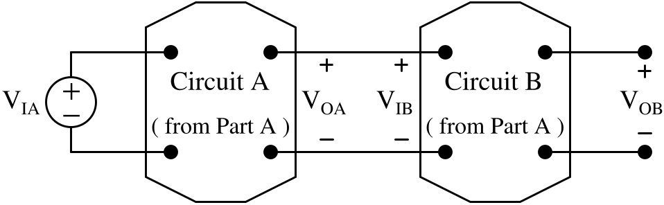
Figure 2 shows that the Circuit A designed in Part A is cascaded with the Circuit B designed in Part A.
Since VIB = VOA, is VOB = KA×KB×VIA? The answer is ‘NO’! WHY?

Do the following parts.

  1. Verify the answer ‘NO’ using a circuit simulator. Include your simulation results in your report.
  2. Explain why the answer is ‘NO’. Provide detailed reasonings in your report using circuit theory, calculations, etc.

REDESIGN Circuit A and/or Circuit B to meet the following design requirements while satisfying the design constraints below.

Design Requirement
  1. In the cascaded circuit, VOA = KA×VIA. KA is the same value given in Table 2 in Circuit Design Part A.
  2. In the cascaded circuit, VOB = KB×VIB. KB is the same value given in Table 2 in Circuit Design Part A.
  3. In the cascaded circuit, VOB = KA×KB×VIA.
Design Constraint
  1. You are allowed to use resistors with resistances within the range of 100 Ω to 400 kΩ only. Refer to APPENDIX II for available resistors.
  2. Use as FEWEST components as possible.

Table of Contents

  • Introduction
    • Safety Rules & Operating Procedures
    • Laboratory Safety Information
    • Troubleshooting Hints
  • Experiments
    • #1: DC Measurements
    • #2: Circuit Analysis Techniques
    • #3: AC Measurements
    • #4: First and Second Order Circuits
  • Projects
    • Project #1 Thevenin’s Theorem
    • Project #2 Circuit Design #1
    • Circuit Design Part A
    • Circuit Design Part B
    • Circuit Design Part C
    • Project #3 AC Load Measurement
    • Project #4 Circuit Element Identification
    • Project #5 Circuit Design #2
  • Appendix
    • I. Lab Component
    • II. List of Available Resistors & Capacitors
    • III. Standard Resistor Color Code

About

Lab Manual Authors:
Dr. Parveen Wahid
Ms. Ya Shen
Dr. Chung Yong Chan

Project Assistant Producers:
Ethan Partidas
Mena Mishriky                                              Ethan Fluhr                                            Isaiah McCarty

Webmasters:
Brandon Cuevas
Garett Goodale

For questions and revision requests, please contact Chung Yong Chan at chungyong.chan@ucf.edu.

Revised March 2023

Theme by Colorlib Powered by WordPress