Skip to content
EEL 3123 Linear Circuits II Lab Manual
  • Introduction
    • Safety Rules & Operating Procedures
    • Laboratory Safety Information
    • Troubleshooting Hints
  • Experiments
    • #1: DC Measurements
    • #2: Circuit Analysis Techniques
    • #3: AC Measurements
    • #4: First and Second Order Circuits
  • Projects
    • Project #1 Thevenin’s Theorem
    • Project #2 Circuit Design #1
      • Circuit Design Part A
      • Circuit Design Part B
      • Circuit Design Part C
    • Project #3 AC Load Measurement
    • Project #4 Circuit Element Identification
    • Project #5 Circuit Design #2
  • Appendix
    • I. Lab Component
    • II. List of Available Resistors & Capacitors
    • III. Standard Resistor Color Code

III. Standard Resistor Color Code

The color code for the resistor value utilizes two digits and a multiplier digit in that order, as shown in Figure A – 1. A fourth band designates the tolerance.
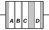
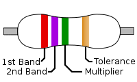
Figure A – 1

The resistance of a resistor with the four bands of color may be written as

R=(A\times 10+B)\times C\pm D

Where A and B are the values of the first and second bands, respectively, C is a multiplier and D is the tolerance. The color code together with multipliers and tolerances are listed in Table A – 1.

Table A – 1 Electronic Color Code

Color Significant figures Multiplier Tolerance
Black 0 ×100 —
Brown 1 ×101 —
Red 2 ×10² ±2%
Orange 3 ×10³ —
Yellow 4 ×10⁴ —
Green 5 ×10⁵ —
Blue 6 ×10⁶ —
Violet 7 ×10⁷ —
Gray 8 ×10⁸ —
White 9 — —
Gold — ×10-1 ±5%
Silver — ×10-2 ±10%
None — — ±20%

For example, if a resistor has four color bands, red-violet-green-gold, as shown in Figure A – 1, then

R = (2 \times 10 + 7) \times 10^5 \pm 5\% = 2.7 \times 10^6 \pm 5\%

Table of Contents

  • Introduction
    • Safety Rules & Operating Procedures
    • Laboratory Safety Information
    • Troubleshooting Hints
  • Experiments
    • #1: DC Measurements
    • #2: Circuit Analysis Techniques
    • #3: AC Measurements
    • #4: First and Second Order Circuits
  • Projects
    • Project #1 Thevenin’s Theorem
    • Project #2 Circuit Design #1
    • Circuit Design Part A
    • Circuit Design Part B
    • Circuit Design Part C
    • Project #3 AC Load Measurement
    • Project #4 Circuit Element Identification
    • Project #5 Circuit Design #2
  • Appendix
    • I. Lab Component
    • II. List of Available Resistors & Capacitors
    • III. Standard Resistor Color Code

About

Lab Manual Authors:
Dr. Parveen Wahid
Ms. Ya Shen
Dr. Chung Yong Chan

Project Assistant Producers:
Ethan Partidas
Mena Mishriky                                              Ethan Fluhr                                            Isaiah McCarty

Webmasters:
Brandon Cuevas
Garett Goodale

For questions and revision requests, please contact Chung Yong Chan at chungyong.chan@ucf.edu.

Revised March 2023

Theme by Colorlib Powered by WordPress